2019年7月1日の法改正により名称が変わりました。まえがきを除き,本規格中の「日本工業規格」を「日本産業規格」に読み替えてください。
日本工業規格 JIS
F 8013-1991
船用電気図記号−通信,計測,
航海及び無線関係
Graphical symbols for electrical apparatus for
marine use engineering drawings−
Communication, instrumentation, navigation and radio
1. 適用範囲 この規格は,船内における電気機器の取付位置,相互の系統などを示す図面に使用する図
記号のうち,通信機器,計測装置,航海計器,無線装置などについて規定する。
備考 この規格の引用規格を,次に示す。
JIS C 0301 電気用図記号
2. 分類 図記号の分類は,次のとおりとする。
(1) 通信及び計測用(一般)
(2) 押ボタン
(3) ベル,ブザー,ホーンなど
(4) ゴング及びモータサイレン
(5) 汽笛
(6) 電話機
(7) 船内指令装置
(8) エンジンテレグラフ
(9) ラダーアングルインジケータ
(10) プロペラ軸回転計
(11) 可変ピッチプロペラ翼角指示器
(12) 計測装置
(13) 火災警報装置及び火災探知装置
(14) ガス検知装置
(15) 監視盤及び制御盤
(16) ジャイロコンパス及び磁気コンパス
(17) オートパイロット
(18) 音響測探機
(19) ログ及びソナー
(20) 風向風速計
(21) クリヤビュースクリーン及びウインドワイパ
2
F 8013-1991
2019年7月1日の法改正により名称が変わりました。まえがきを除き,本規格中の「日本工業規格」を「日本産業規格」に読み替えてください。
(22) 電気時計
(23) 電波航法装置
(24) 無線装置及び娯楽装置
(25) アンテナ
3. 図記号の用い方 図記号の用い方は,次による。
(1) 図記号の大きさを変えることは自由であるが,なるべく相似な形としなければならない。ただし,線
の太さを変えて用途を区別するなどの応用を行ってもよい。
(2) 必要がある場合には,図記号に番号などを併記して別に対照表を付け,その区別を明示してもよい。
(3) 図記号は,性能類似の他のものに準用することができるが,この場合には,符号その他適当な方法に
よって,その性能を明らかにする必要がある。
(4) この規格に定めてないものは,図記号の組合せ,文字・記号の併記などによって表すことを推奨する。
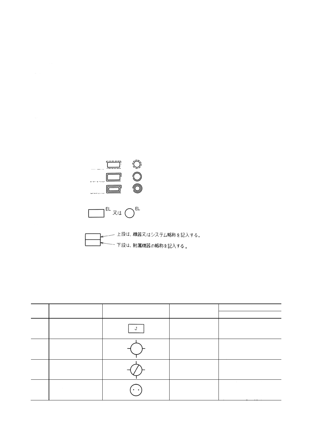
(5) 特に,埋込形,防水形又は装飾形を区別する必要がある場合は,次のように表す。
(a) 埋込形
又は
(b) 防水形
又は
(c) 装飾形
又は
(6) 照明装置付の表示盤,指示器類は,次のように表す。
(7) 附属機器を表す必要がある場合は,次のように表す。
(8) 図記号に※を付けたものは,JIS C 0301と同じものを示す。その他JIS C 0301の基本図記号にあるも
のは省略してある。
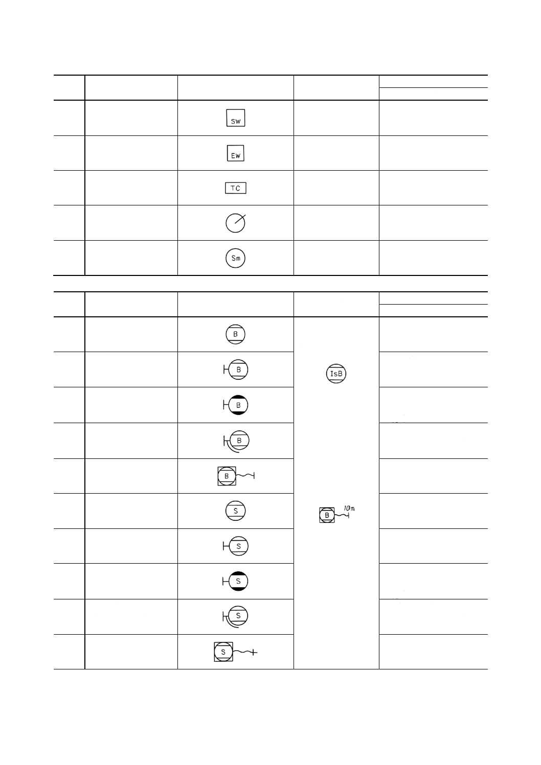
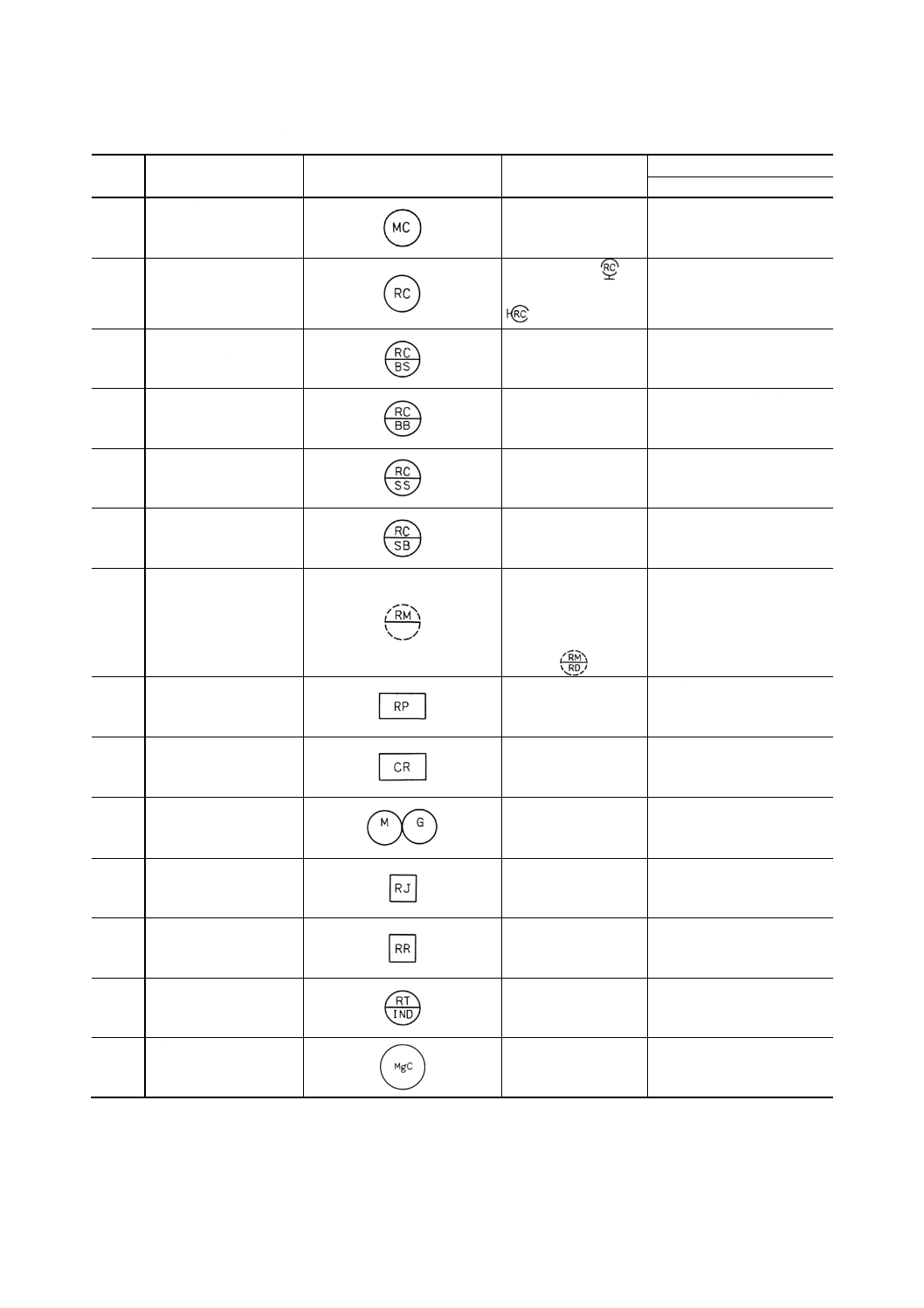
4. 名称及び図記号 名称及び図記号は,次のとおりとする。
なお,参考として英文名称を示す。
(1) 通信及び計測用(一般)
番号
名称
図記号
備考
参考
英文名称
1.1
接続箱
joint box,
junction box
1.2
接続箱
(非防水)
joint box,
junction box (non-watertight
type)
1.3
接続箱
(防水)
joint box,
junction box (watertight type)
1.4
レセプタクル2極
(非防水)
receptacle 2 pole(米)
socket outlet 2 pole(英)
(non-watertight type)
3
F 8013-1991
2019年7月1日の法改正により名称が変わりました。まえがきを除き,本規格中の「日本工業規格」を「日本産業規格」に読み替えてください。
番号
名称
図記号
備考
参考
英文名称
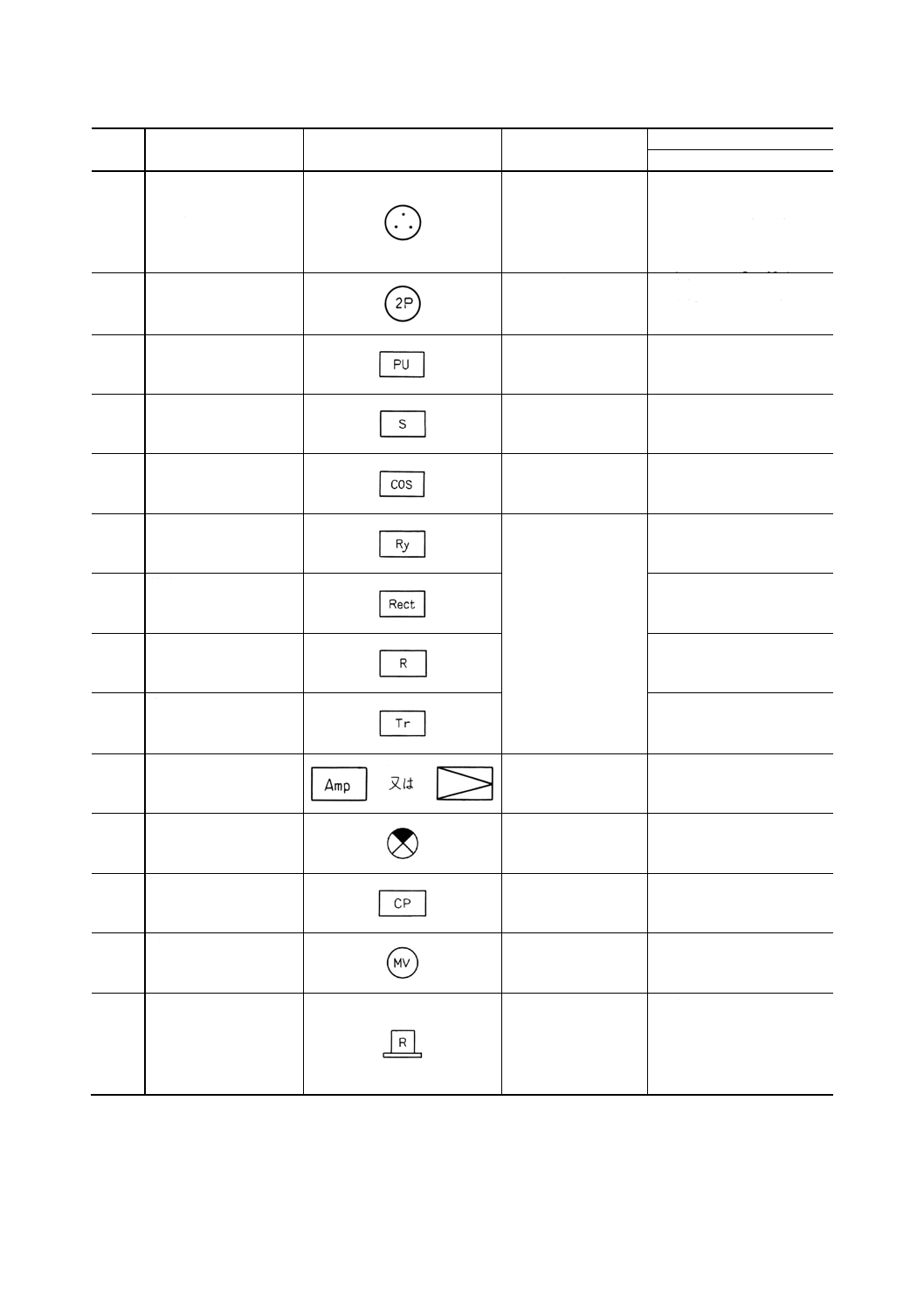
1.5
レセプタクル2極接地
極付
(非防水)
receptacle 2 pole with
earthing contact(米)
socket outlet 2 pole with
earthing contact(英)
(non-watertight type)
1.6
特形レセプタクル
2極の場合を表す。
special type receptacle(米)
special type socket outlet
(英)
1.7
電源箱
power unit
1.8
開閉器箱
switch box
1.9
切換開閉器箱
change over switch box
1.10
継電器
箱入りの場合も同じ
図記号で表す。
relay
1.11
整流器
rectifier
1.12
抵抗器
resistor
1.13
変圧器
transformer
1.14
増幅器
amplifier
1.15
光度加減器
dimmer
1.16
管制盤
control panel
1.17
電磁弁
magnetic valve
1.18
回転灯
枠内には色を表示す
る。
R=Red
A=Amber
G=Green
rotating lamp
4
F 8013-1991
2019年7月1日の法改正により名称が変わりました。まえがきを除き,本規格中の「日本工業規格」を「日本産業規格」に読み替えてください。
(2) 押ボタン
番号
名称
図記号
備考
参考
英文名称
2.1
押ボタンスイッチ
(非防水)
push button switch
(non-watertight type)
2.2
押ボタンスイッチ
(防水)
push button switch
(watertight type)
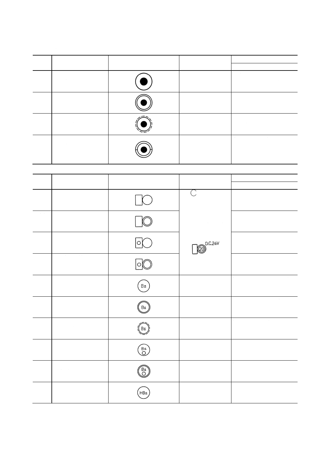
2.3
押ボタンスイッチ
(埋込形)
push button switch (flush
type)
2.4
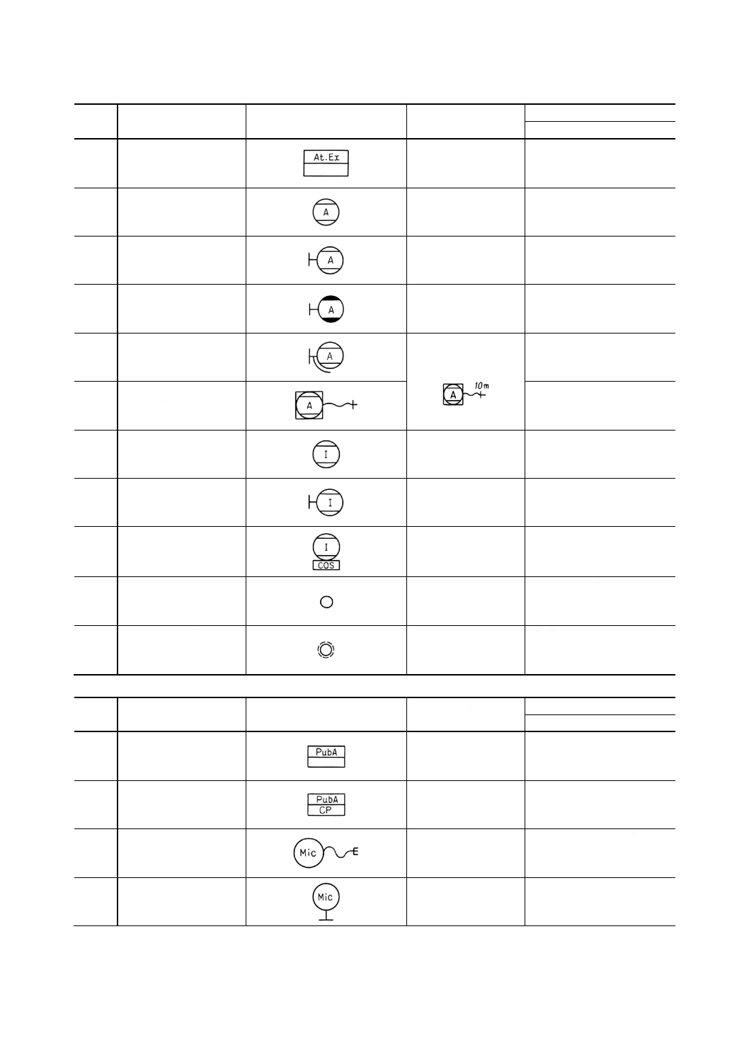
耐圧防爆押ボタンスイ
ッチ
flameproof push button
switch(英)
explosionproof push button
switch(米)
(3) ベル,ブザー,ホーンなど
番号
名称
図記号
備考
参考
英文名称
3.1
ベル
(非防水)
1.
の中にベルの
直径を単位cmで
表した数字を記
入する。
2. 電圧を表す必要の
ある場合は、右上
に記入する。
例
bell (non-watertight type)
3.2
ベル
(防水)
bell (watertight type)
3.3
ベル表示灯付
(非防水)
bell with pilot lamp
(non-watertight type)
3.4
ベル表示灯付
(防水)
bell with pilot lamp
(watertight type)
3.5
ブザー
(非防水)
buzzer (non-watertight type)
3.6
ブザー
(防水)
buzzer (watertight type)
3.7
ブザー
(埋込形)
buzzer (flush type)
3.8
ブザー表示灯付
(非防水)
buzzer with pilot lamp
(non-watertight type)
3.9
ブザー表示灯付
(防水)
buzzer with pilot lamp
(watertight type)
3.10
ホーンブザー
(非防水)
horn buzzer (non-watertight
type)
5
F 8013-1991
2019年7月1日の法改正により名称が変わりました。まえがきを除き,本規格中の「日本工業規格」を「日本産業規格」に読み替えてください。
番号
名称
図記号
備考
参考
英文名称
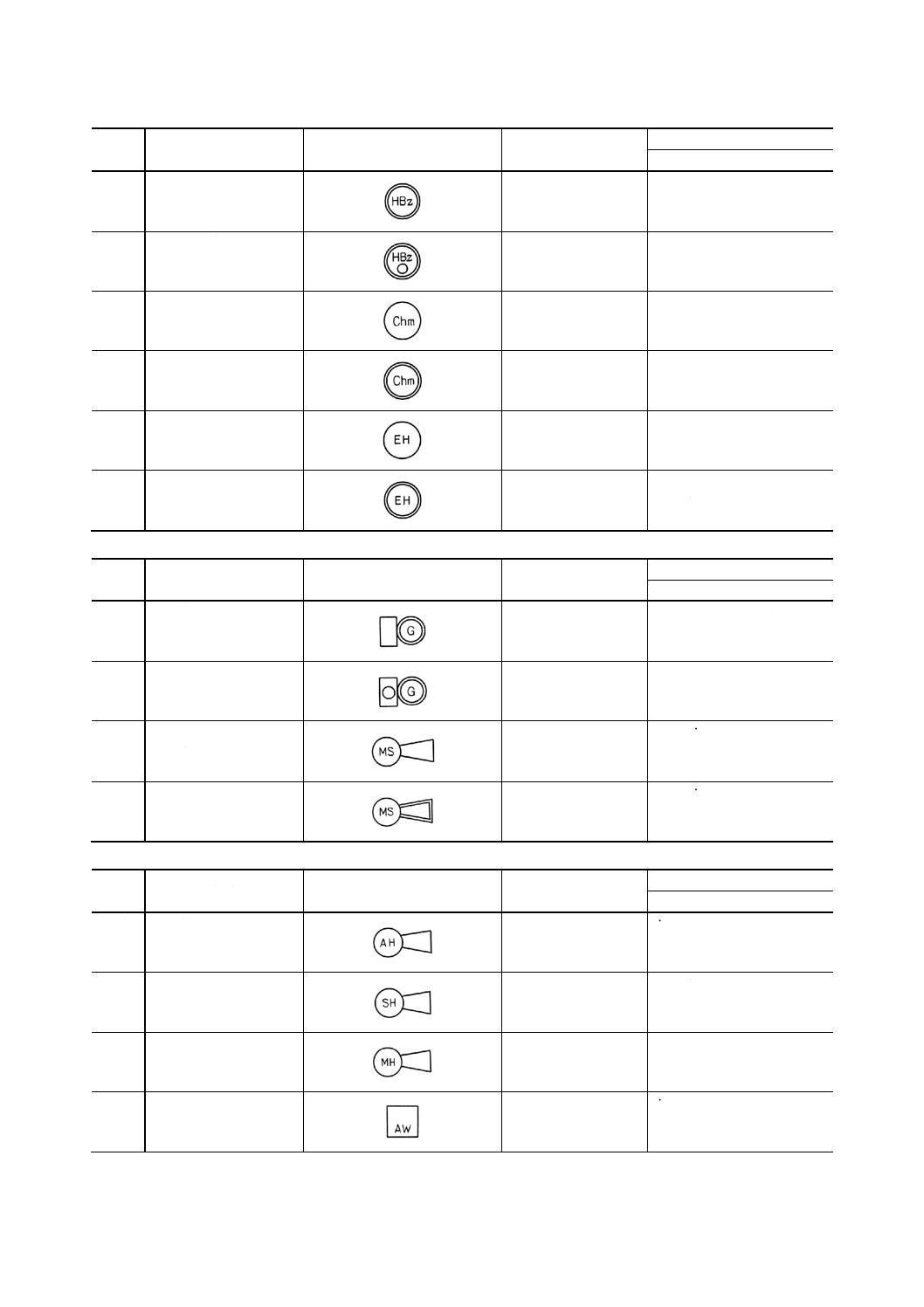
3.11
ホーンブザー
(防水)
horn buzzer (watertight type)
3.12
ホーンブザー表示灯付
(防水)
horn buzzer with pilot lamp
(watertight type)
3.13
チャイム
(非防水)
chime (non-watertight type)
3.14
チャイム
(防水)
chime (watertight type)
3.15
電子ホーン
(非防水)
electronic horn
(non-watertight type)
3.16
電子ホーン
(防水)
electronic horn (watertight
type)
(4) ゴング及びモータサイレン
番号
名称
図記号
備考
参考
英文名称
4.1
ゴング
(防水)
gong (watertight type)
4.2
ゴング表示灯付
(防水)
gong with pilot lamp
(watertight type)
4.3
モータサイレン
(非防水)
motor siren (non-watertight
type)
4.4
モータサイレン
(防水)
motor siren (watertight type)
(5) 汽笛
番号
名称
図記号
備考
参考
英文名称
5.1
エアホーン
air horn
5.2
スチームホーン
steam horn
5.3
モータホーン
motor horn
5.4
気笛
air whistle
6
F 8013-1991
2019年7月1日の法改正により名称が変わりました。まえがきを除き,本規格中の「日本工業規格」を「日本産業規格」に読み替えてください。
番号
名称
図記号
備考
参考
英文名称
5.5
汽笛
steam whistle
5.6
電気式気笛
electric whistle
5.7
タイムコントローラ
time controller
5.8
ダイヤルスイッチ
dial switch
5.9
スモークエミッタ
smoke emitter
(6) 電話機
番号
名称
図記号
備考
参考
英文名称
6.1
共電式電話機
(卓上形)
本質安全形のものは,
記号の前にIsを付け
る。
例
common battery telephone
(desk type)
6.2
共電式電話機
(壁掛形)
common battery telephone
(wall type)
6.3
共電式電話機
(壁掛両耳形)
common battery telephone
with sub-receiver (wall
type)
6.4
共電式電話機
(ヘッドホン形)
common battery telephone
with headset (wall type)
6.5
共電式電話機
(移動形)
コード長さを表す必
要がある場合は,右上
に記入する。
例
common battery telephone
(portable type)
6.6
無電池式電話機
(卓上形)
sound powered telephone
(desk type)
6.7
無電池式電話機
(壁掛形)
sound powered telephone
(wall type)
6.8
無電池式電話機
(壁掛両耳形)
sound powered telephone
with sub-receiver (wall
type)
6.9
無電池式電話機
(ヘッドホン形)
sound powered telephone
with headset (wall type)
6.10
無電池式電話機
(移動形)
sound powered telephone
(portable type)
7
F 8013-1991
2019年7月1日の法改正により名称が変わりました。まえがきを除き,本規格中の「日本工業規格」を「日本産業規格」に読み替えてください。
番号
名称
図記号
備考
参考
英文名称
6.11
自動電話交換機
下の欄に回線数を記
入する。
auto telephone exchanger
6.12
自動式電話機
(卓上形)
auto telephone (desk type)
6.13
自動式電話機
(壁掛形)
auto telephone (wall type)
6.14
自動式電話機
(壁掛両耳形)
auto telephone with
sub-receiver (wall type)
6.15
自動式電話機
(ヘッドホン形)
コード長さを表す必
要がある場合は,右上
に記入する。
auto telephone with headset
(wall type)
6.16
自動式電話機
(移動形)
auto telephone (portable type)
6.17
インターホン
(卓上形)
interphone (desk type)
6.18
インターホン
(壁掛形)
interphone (wall type)
6.19
インターホン
(切換スイッチ付卓上
形)
interphone with change over
switch (desk type)
6.20
電話機用ローゼット
telephone rosette
6.21
電話機用ローゼット
(埋込形)
telephone rosette (flush type)
(7) 船内指令装置
番号
名称
図記号
備考
参考
英文名称
7.1
船内指令装置増幅器
枠内に増幅器出力
(W) を記入する。
public addressor amplifier
7.2
船内指令装置管制盤
public addressor control panel
7.3
マイクロホン
(移動形)
microphone (hand type)
7.4
マイクロホン
(卓上形)
microphone (desk type)
8
F 8013-1991
2019年7月1日の法改正により名称が変わりました。まえがきを除き,本規格中の「日本工業規格」を「日本産業規格」に読み替えてください。
番号
名称
図記号
備考
参考
英文名称
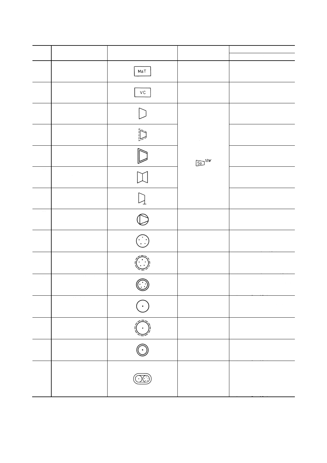
7.5
整合変圧器
matching transformer
7.6
音量調整器
volume control box
7.7
スピーカ
(一般)
容量を表す必要があ
る場合は,右上にWで
記入する。
また,明確にする必要
がある場合は,枠内に
Spの文字を記入して
もよい。
例
speaker (general)
7.8
スピーカ
(埋込形)
speaker (flush type)
7.9
スピーカ
(防水形)
speaker (watertight type)
7.10
スピーカ
(両面形)
speaker (double face type)
7.11
スピーカ
(回転形)
speaker (rotary type)
7.12
マイクロホンスピーカ
microphone speaker
7.13
マイクロホン接続座
(非防水形)
microphone receptacle(米)
microphone socket outlet(英)
(non-watertight type)
7.14
マイクロホン接続座
(非防水埋込形)
microphone receptacle(米)
microphone socket outlet(英)
(non-watertight flush type)
7.15
マイクロホン接続座
(防水形)
microphone receptacle(米)
microphone socket outlet(英)
(watertight type)
7.16
スピーカ接続座
(非防水形)
speaker receptacle(米)
speaker socket outlet(英)
(non-watertight type)
7.17
スピーカ接続座
(非防水埋込形)
speaker receptacle(米)
speaker socket outlet(英)
(non-watertight flush type)
7.18
スピーカ接続座
(防水形)
speaker receptacle(米)
speaker socket outlet(英)
(watertight type)
7.19
マイクロホンスピーカ
接続座
(防水形)
microphone and speaker
receptacles(米)
microphone and speaker
socket outlets(英)
(watertight type)
9
F 8013-1991
2019年7月1日の法改正により名称が変わりました。まえがきを除き,本規格中の「日本工業規格」を「日本産業規格」に読み替えてください。
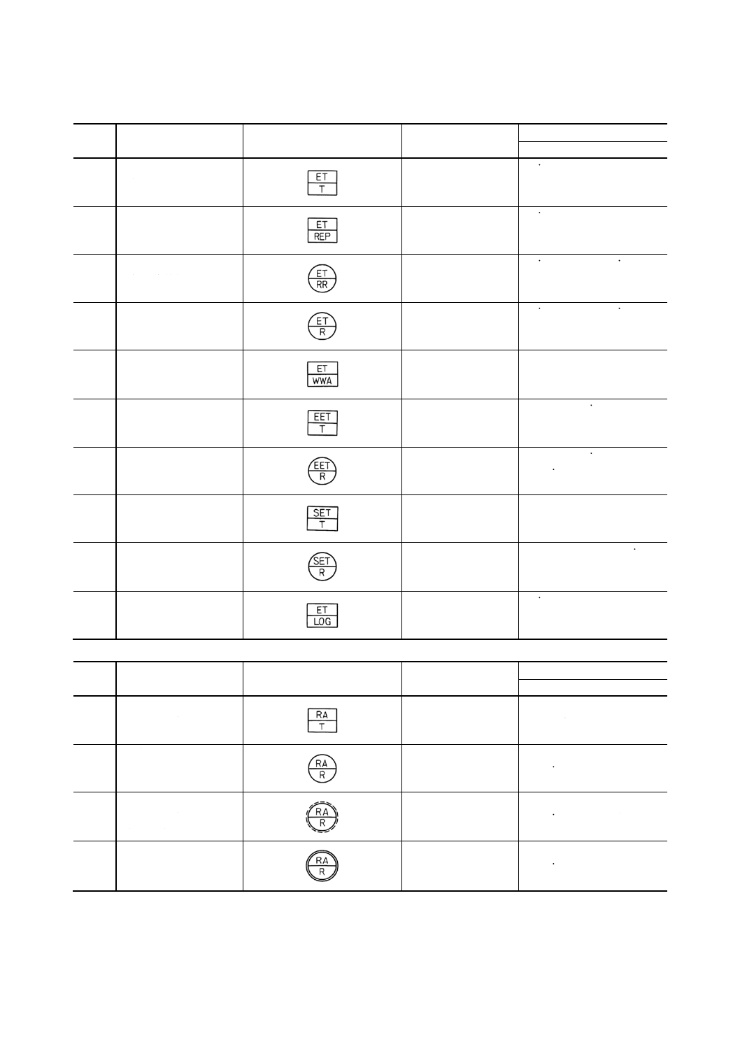
(8) エンジンテレグラフ
番号
名称
図記号
備考
参考
英文名称
8.1
エンジンテレグラフ発
信器
engine telegraph transmitter
8.2
エンジンテレグラフ発
信器レピータ
engine telegraph repeater
8.3
エンジンテレグラフ受
信器応答付
engine telegraph receiver
with reply
8.4
エンジンテレグラフ受
信器
engine telegraph receiver
8.5
誤動作警報発信器
wrong way alarm transmitter,
wrong operation alarm
transmitter
8.6
非常用エンジンテレグ
ラフ発信器
emergency engine telegraph
transmitter
8.7
非常用エンジンテレグ
ラフ受信器
emergency engine telegraph
receiver
8.8
サブエンジンテレグラ
フ発信器
subengine telegraph
transmitter
8.9
サブエンジンテレグラ
フ受信器
subengine telegraph receiver
8.10
エンジンテレグラフロ
ガー
engine telegraph logger
(9) ラダーアングルインジケータ
番号
名称
図記号
備考
参考
英文名称
9.1
ラダーアングルインジ
ケータ発信器
rudder angle indicator
transmitter
9.2
ラダーアングルインジ
ケータ受信器
rudder angle indicator
receiver
9.3
ラダーアングルインジ
ケータ受信器
(埋込形)
rudder angle indicator
receiver (flush type)
9.4
ラダーアングルインジ
ケータ受信器
(防水形)
rudder angle indicator
receiver (watertight type)
10
F 8013-1991
2019年7月1日の法改正により名称が変わりました。まえがきを除き,本規格中の「日本工業規格」を「日本産業規格」に読み替えてください。
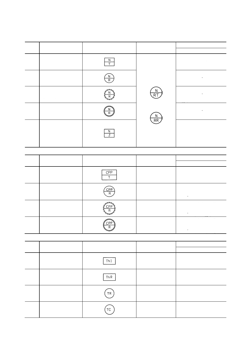
(10) プロペラ軸回転計
番号
名称
図記号
備考
参考
英文名称
10.1
プロペラ軸回転計発信
器
積算回転計付きのも
のは,記号の次にR
を,また回転方向指示
器付きの場合は記号
の後にTを付ける。
例
propeller shaft revolution
indicator transmitter
10.2
プロペラ軸回転計受信
器
propeller shaft revolution
indicator receiver
10.3
プロペラ軸回転計受信
器
(埋込形)
propeller shaft revolution
indicator receiver (flush
type)
10.4
プロペラ軸回転計受信
器
(防水形)
propeller shaft revolution
indicator receiver
(watertight type)
10.5
プロペラ軸回転計接続
箱
propeller shaft revolution
indicator joint box
propeller shaft,
revolution indicator junction
box
(11) 可変ピッチプロペラ翼角指示器
番号
名称
図記号
備考
参考
英文名称
11.1
可変ピッチプロペラ
翼角指示器発信器
controllable pitch propeller
pitch angle indicator
transmitter
11.2
可変ピッチプロペラ
翼角指示器受信器
controllable pitch propeller
pitch angle indicator
receiver
11.3
可変ピッチプロペラ
翼角指示器受信器
(埋込形)
controllable pitch propeller
pitch angle indicator
receiver (flush type)
11.4
可変ピッチプロペラ
翼角指示器受信器
(防水形)
controllable pitch propeller
pitch angle indicator
receiver (watertight type)
(12) 計測装置
番号
名称
図記号
備考
参考
英文名称
12.1
温度指示器
thermo-indicator
12.2
温度記録器
thermo-recorder
12.3
測温抵抗体
resistance bulb
12.4
熱電対
thermo-couple
11
F 8013-1991
2019年7月1日の法改正により名称が変わりました。まえがきを除き,本規格中の「日本工業規格」を「日本産業規格」に読み替えてください。
番号
名称
図記号
備考
参考
英文名称
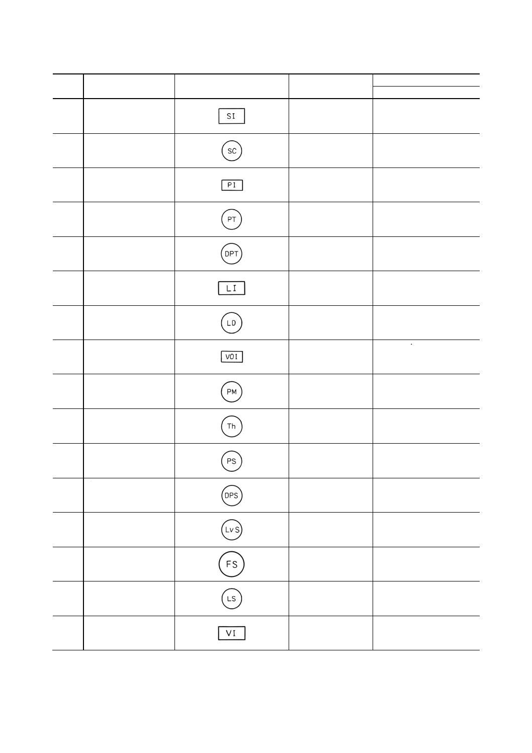
12.5
検塩計指示器
salinity indicator
12.6
検塩計電極
salinity cell
12.7
圧力指示器
pressure indicator
12.8
圧力発信器
pressure transmitter
12.9
差圧発信器
differential pressure
transmitter
12.10 液面指示器
level indicator
12.11 液面検出器
level detector
12.12 開度指示計
valve opening indicator,
valve position indicator
12.13 ポテンショメータ
Potentiometer
12.14 温度スイッチ
thermostat
12.15 圧力スイッチ
pressure switch
12.16 差圧スイッチ
differential pressure switch
12.17 液面スイッチ
level switch
12.18 流量スイッチ
flow switch
12.19 リミットスイッチ
limit switch
12.20 振動指示器
vibration indicator
12
F 8013-1991
2019年7月1日の法改正により名称が変わりました。まえがきを除き,本規格中の「日本工業規格」を「日本産業規格」に読み替えてください。
番号
名称
図記号
備考
参考
英文名称
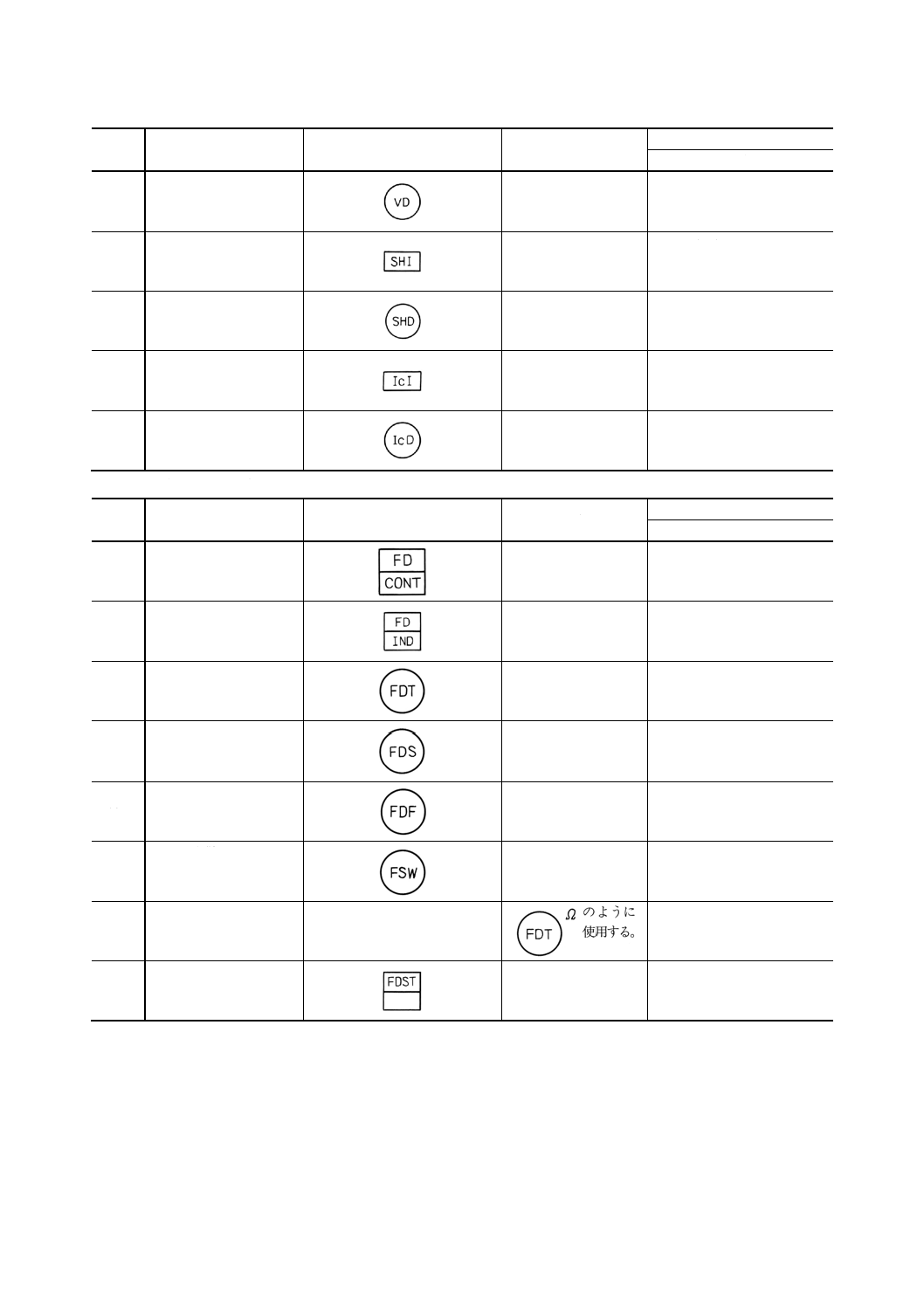
12.21 振動検出器
vibration detector
12.22 軸出力指示器
shaft output indicator
12.23 軸出力検出器
shaft output detector
12.24 電気式傾斜指示器
electro inclination indicator
12.25 電気式傾斜検出器
electro inclination detector
(13) 火災警報装置及び火災探知装置
番号
名称
図記号
備考
参考
英文名称
13.1
火災制御盤
fire alarm panel,
firecontrol panel
13.2
火災表示盤
fire indicating panel
13.3
熱探知器
thermal detector,
heat detector
13.4
煙探知器
smoke detector
13.5
火災探知器
flame detector
13.6
手動火災警報器
manual call fire switch
13.7
終端抵抗器
※
Ω
end of line resister
13.8
煙管式火災探知器
smoke tube tybe fire detector
13
F 8013-1991
2019年7月1日の法改正により名称が変わりました。まえがきを除き,本規格中の「日本工業規格」を「日本産業規格」に読み替えてください。
(14) ガス検知装置
番号
名称
図記号
備考
参考
英文名称
14.1
ガス検知器制御盤
gas detector control panel
14.2
ガス検知器
gas detector head
14.3
ガス検知器用吸引ファ
ン
extract fan for gas detector
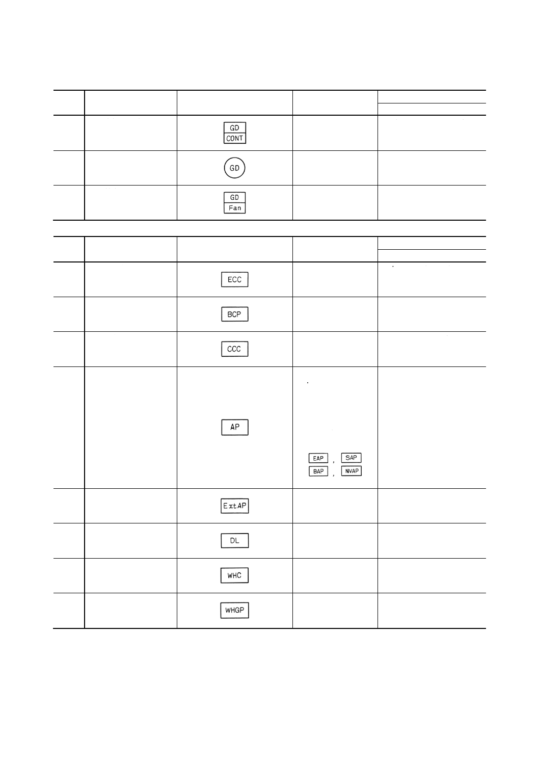
(15) 監視盤及び制御盤
番号
名称
図記号
備考
参考
英文名称
15.1
機関部制御盤
engine control console
15.2
ボイラ制御盤
boiler control panel
15.3
荷役制御盤
Cargo control console
15.4
警報盤
(一般)
必要に応じて
engineers, alarm
panel, steering
alarm panel, boiler
alarm panel, no-voltage
alarm panel
などは,それぞれ
などとする。
alarm panel (general)
15.5
延長警報盤
extension alarm panel
15.6
データロガー
data logger
15.7
操だ(舵)室制御盤
wheel house control console
15.8
操だ(舵)室集合計器盤
wheel house group panel
14
F 8013-1991
2019年7月1日の法改正により名称が変わりました。まえがきを除き,本規格中の「日本工業規格」を「日本産業規格」に読み替えてください。
(16) ジャイロコンパス及び磁気コンパス
番号
名称
図記号
備考
参考
英文名称
16.1
主羅針儀
master compass
16.2
従羅針儀
(一般)
スタンド形は
ま
た,ブラケット形は
で表してもよい。
repeater compass (general)
16.3
従羅針儀ベアリング用
スタンド形
repeater compass bearing
stand type
16.4
従羅針儀ベアリング用
ブラケット形
repeater compass bearing
bracket type
16.5
従羅針儀操だ(舵)用
スタンド形
repeater compass steering
stand type
16.6
従羅針儀操だ(舵)用ブ
ラケット形
repeater compass steering
bracket type
16.7
従羅針儀レピータモー
タ
枠内に用途を表す記
号を記入する。
例 レーダ用レピ
ータモータ
repeater motor
16.8
従羅針儀配電盤
repeater panel
16.9
コースレコーダ
course recorder
16.10 電動発電機
文字の下に交流の場
合は〜,直流の場合は
− を記入する。
motor generator
16.11 従羅針儀接続箱
repeater joint box,
repeater junction box
16.12 従羅針儀接続座
repeater receptacle
16.13 ターンレイトインディ
ケータ
rate of turn indicator
16.14 磁気コンパス
magnetic compass
15
F 8013-1991
2019年7月1日の法改正により名称が変わりました。まえがきを除き,本規格中の「日本工業規格」を「日本産業規格」に読み替えてください。
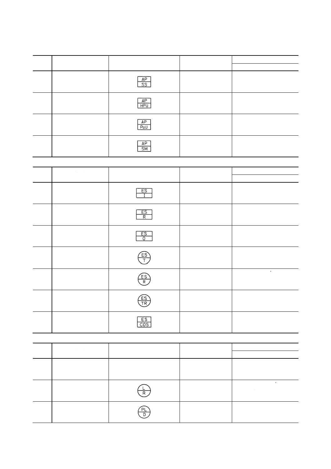
(17) オートパイロット
番号
名称
図記号
備考
参考
英文名称
17.1
操だ(舵)スタンド
steering stand
17.2
ポンプユニット
hydraulic pump unit
17.3
パワーユニット
Power unit
17.4
サーボモータ
servo-motor
(18) 音響測探機
番号
名称
図記号
備考
参考
英文名称
18.1
音響測深機指示器
echo-sounder indicator
18.2
音響測深機記録器
echo-sounder recorder
18.3
音響測深機発振器
echo-sounder oscillator
18.4
音響測深機送波器
echo-sounder transmitter
18.5
音響測深機受波器
echo-sounder receiver
18.6
音響測深機送受波器
echo-sounder transducer
18.7
音響測深機送受波器切
換器
echo-sounder transducer
change over switch
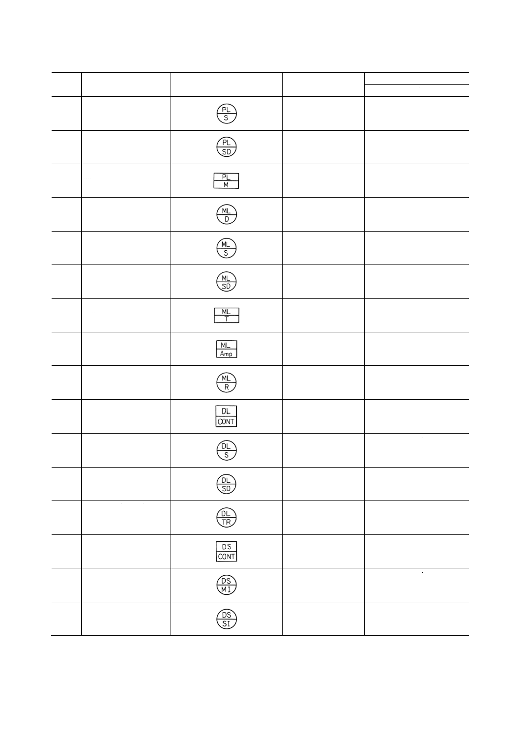
(19) ログ及びソナー
番号
名称
図記号
備考
参考
英文名称
19.1
電気ログ発信器
(一般)
electric ship log transmitter
(general)
19.2
電気ログ受信器
(一般)
electric ship log receiver
(general)
19.3
圧力ログ航程指示器
pressure log distance indicator
16
F 8013-1991
2019年7月1日の法改正により名称が変わりました。まえがきを除き,本規格中の「日本工業規格」を「日本産業規格」に読み替えてください。
番号
名称
図記号
備考
参考
英文名称
19.4
圧力ログ速度指示器
pressure log speed indicator
19.5
圧力ログ速度航程指示
器
pressure log speed & distance
indicator
19.6
圧力ログ速度航程発信
器
pressure log master log
19.7
電磁ログ航程指示器
electro-magnetic log distance
indicator
19.8
電磁ログ速度指示器
electro-magnetic log speed
indicator
19.9
電磁ログ速度航程指示
器
electro-magnetic log speed &
distance indicator
19.10 電磁ログ速度航程発信
器
electro-magnetic log
transmitter
19.11 電磁ログ増幅器
electro-magnetic log amplifier
19.12 電磁ログ測程かん(桿)
electro-magnetic log rodmeter
19.13 ドプラログ制御盤
doppler log control panel
19.14 ドプラログ速度指示器
doppler log speed indicator
19.15 ドプラログ速度航程指
示器
doppler log speed & distance
indicator
19.16 ドプラログ送受波器
doppler log transducer
19.17 ドプラソナー制御盤
doppler sonar control panel
19.18 ドプラソナー主表示器
doppler sonar main indicator
19.19 ドプラソナー副表示器
doppler sonar sub indicator
17
F 8013-1991
2019年7月1日の法改正により名称が変わりました。まえがきを除き,本規格中の「日本工業規格」を「日本産業規格」に読み替えてください。
番号
名称
図記号
備考
参考
英文名称
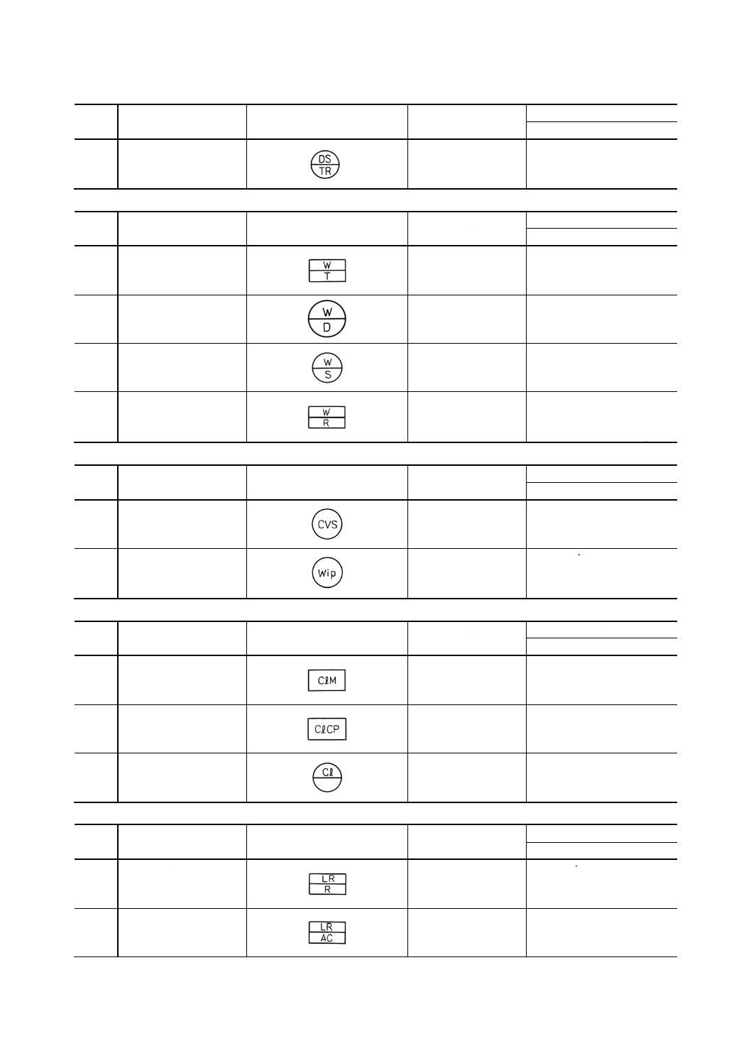
19.20 ドプラソナー送受波器
doppler sonar transducer
(20) 風向風速計
番号
名称
図記号
備考
参考
英文名称
20.1
風向風速計発信器
wind direction & speed
transmitter
20.2
風向指示器
wind direction indicator,
anemoscope
20.3
風速指示器
wind speed indicator,
anemometer
20.4
風向風速記録器
wind direction & speed
recorder,
anemometer & anemoscope
(21) クリヤビュースクリーン及びウインドワイパ
番号
名称
図記号
備考
参考
英文名称
21.1
クリヤビュースクリー
ン
clear-view screen
21.2
ウインドワイパ
window wiper
(22) 電気時計
番号
名称
図記号
備考
参考
英文名称
22.1
親時計
master clock
22.2
電気時計管制盤
electric clock control panel
22.3
子時計
枠内に針数を表す数
字を記入する。
slave clock
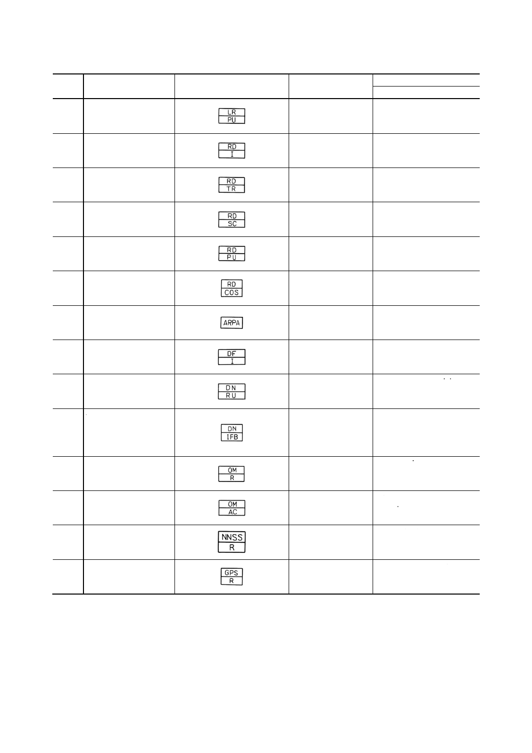
(23) 電波航法装置
番号
名称
図記号
備考
参考
英文名称
23.1
ロラン受信機
loran receiver
23.2
ロランアンテナカプラ
antenna coupler for loran
18
F 8013-1991
2019年7月1日の法改正により名称が変わりました。まえがきを除き,本規格中の「日本工業規格」を「日本産業規格」に読み替えてください。
番号
名称
図記号
備考
参考
英文名称
23.3
ロラン電源箱
loran power unit
23.4
レーダ指示器
radar indicator
23.5
レーダ送受信機
radar transceiver
23.6
走査空中線
(レーダスキャナ)
radar scanner
23.7
レーダ電源箱
radar power unit
23.8
レーダ切換スイッチ
radar interchange switch
23.9
自動衝突予防援助装置
automatic radar plotting aids
23.10 無線方位測定機
radio direction finder
23.11 デッカナビゲータ受信
機
Decca navigator receiving
Unit
23.12 デッカナビゲータブラ
ウンボックス用イン
ターフェイスユニッ
ト
Decca navigator interface unit
for brown box
23.13 オメガ受信機
omega receiver
23.14 オメガ受信機用アンテ
ナカプラ
antenna coupler for omega
receiver
23.15 NNSS
navy navigation satellite
system
23.16 GPS
grobal positioning system
19
F 8013-1991
2019年7月1日の法改正により名称が変わりました。まえがきを除き,本規格中の「日本工業規格」を「日本産業規格」に読み替えてください。
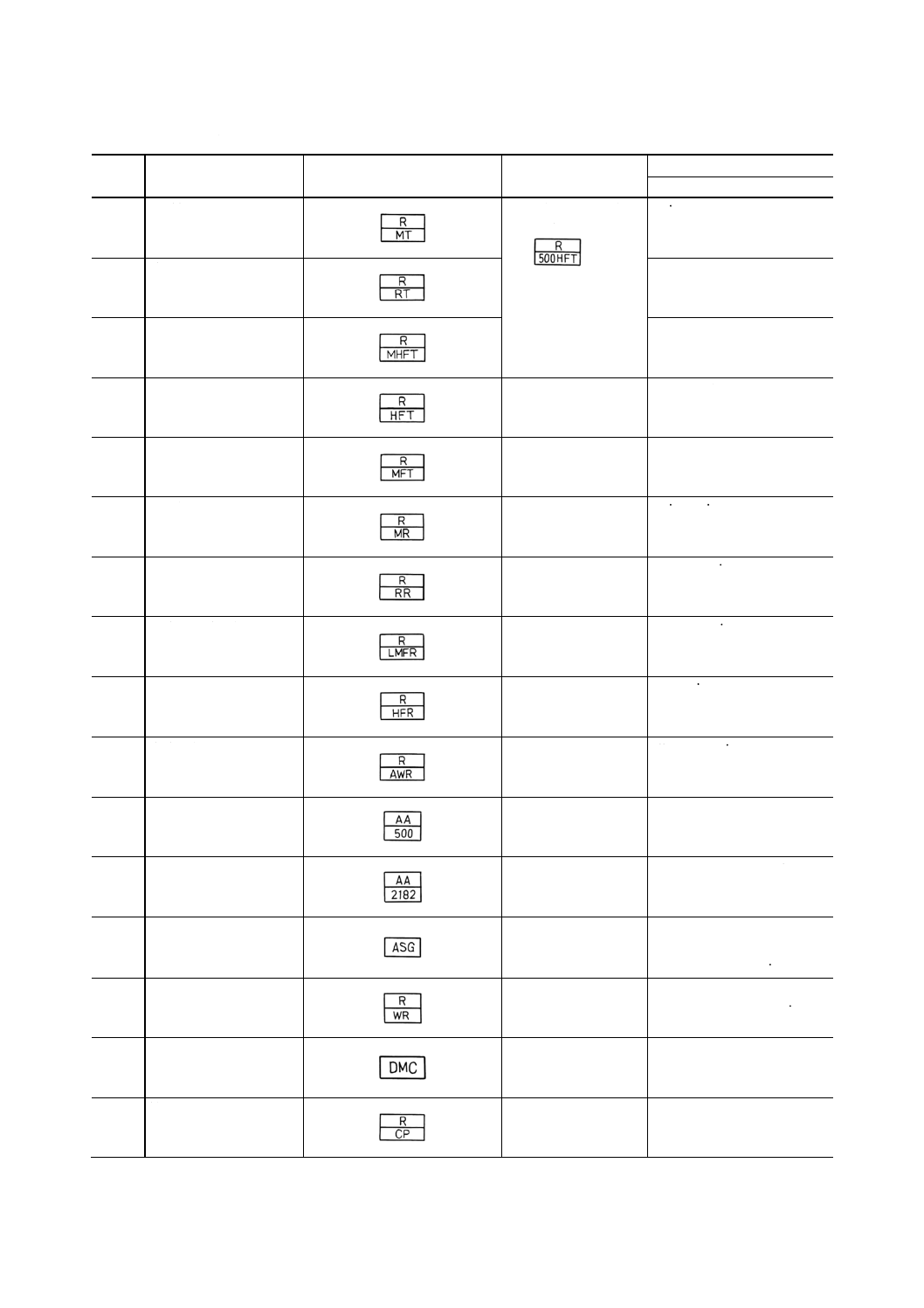
(24) 無線装置及び娯楽装置
番号
名称
図記号
備考
参考
英文名称
24.1
主送信機
出力(kW又はW)を
表す場合は
例
のようにする。
main transmitter
24.2
補助送信機
reserve transmitter
24.3
中波・短波送信機
MF-HF transmitter
24.4
短波送信機
HF transmitter
24.5
中波送信機
MF transmitter
24.6
主受信機
main receiver
24.7
補助受信機
reserve receiver
24.8
長波・中波受信機
LF-MF receiver
24.9
短波受信機
HF receiver
24.10 全波受信機
all wave receiver
24.11 警急自動受信機
Radio telegraph auto-alarm
24.12 無線電話警急自動受信
機
Radio telephone auto-alarm
24.13 警急自動電話装置
Automatic devices for
Generating the radio
Telephone alarm sign
24.14 無線電話遭難周波数聴
取受信機
Radio telephone distress
Frequency watch receiver
24.15 警報管制器
Distress message controller
24.16 管制盤
(一般)
Control panel (general)
20
F 8013-1991
2019年7月1日の法改正により名称が変わりました。まえがきを除き,本規格中の「日本工業規格」を「日本産業規格」に読み替えてください。
番号
名称
図記号
備考
参考
英文名称
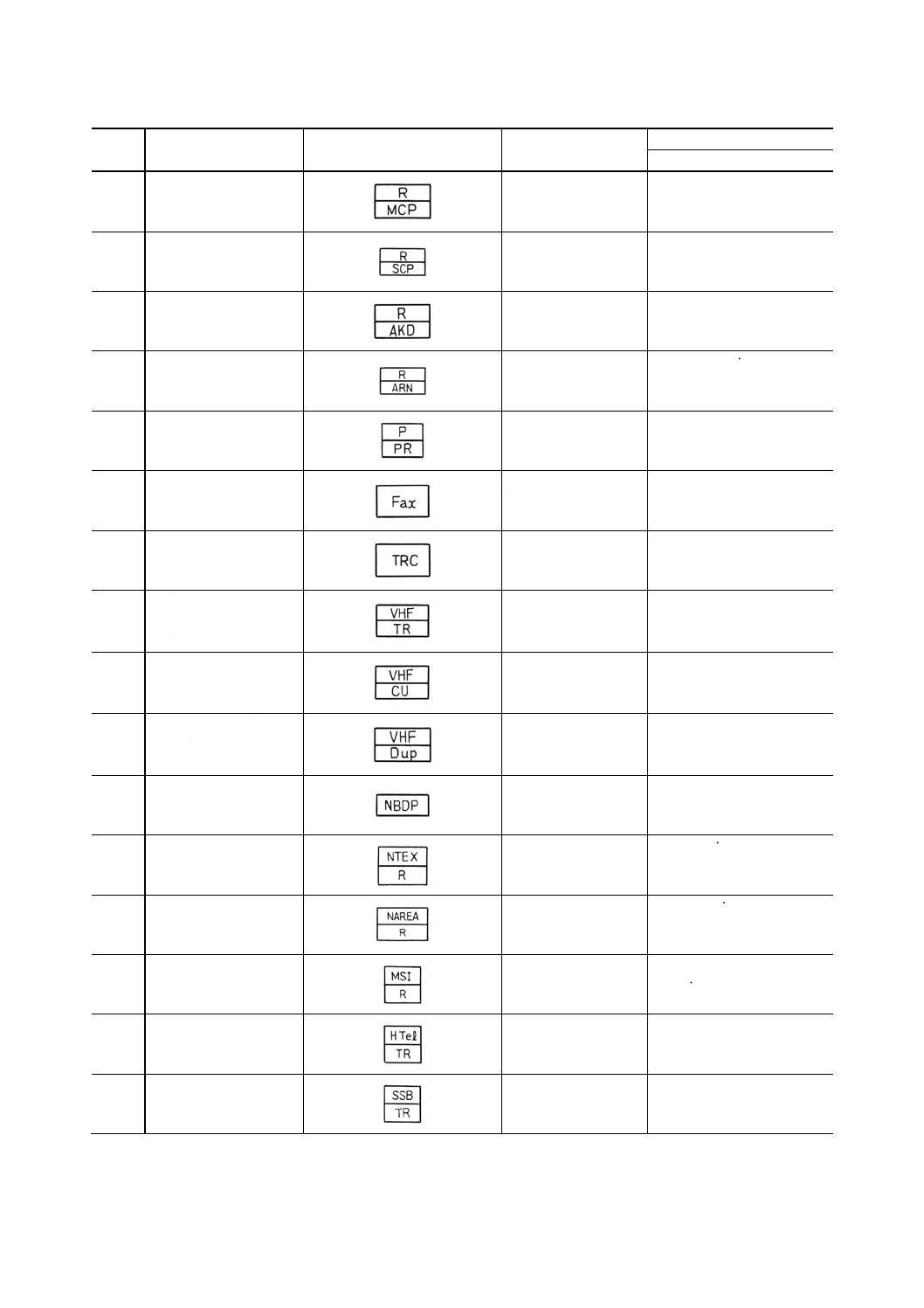
24.17 主管制盤
Main control panel
24.18 副管制盤
Sub-control panel
24.19 警急信号自動電鍵装置
Automatic radio telegraph
Alarm signal keying device
24.20 定時放送自動受信機
Automatic receiver for news
24.21 生存艇用携帯無線装置
Portable radio apparatus for
Survival craft
24.22 ファクシミリ
気象用は,先頭にWを
付す。
facsimile
24.23 テープレコーダ
tape recorder
24.24 国際VHF
無線電話装置送受信
機
international VHF radio
telephone equipment
transceiver
24.25 国際VHF
無線電話装置コント
ロールユニット
international VHF radio
telephone equipment
control unit
24.26
国際VHF無線電話装
置デュープレックス
フィルタ
international VHF radio
telephone equipment duplex
filter
24.27 狭帯域直接印刷電信装
置
narrow band direct printing
telegraph
24.28 NAVTEX受信装置
navtex receiver
24.29 NAVAREA受信装置
navarea receiver
24.30 海上安全情報受信機
maritime safety information
receiver
24.31 船舶無線電話装置送受
信機
harbour radio telephone
equipment transceiver
24.32 SSB送受信機
SSB transceiver
21
F 8013-1991
2019年7月1日の法改正により名称が変わりました。まえがきを除き,本規格中の「日本工業規格」を「日本産業規格」に読み替えてください。
番号
名称
図記号
備考
参考
英文名称
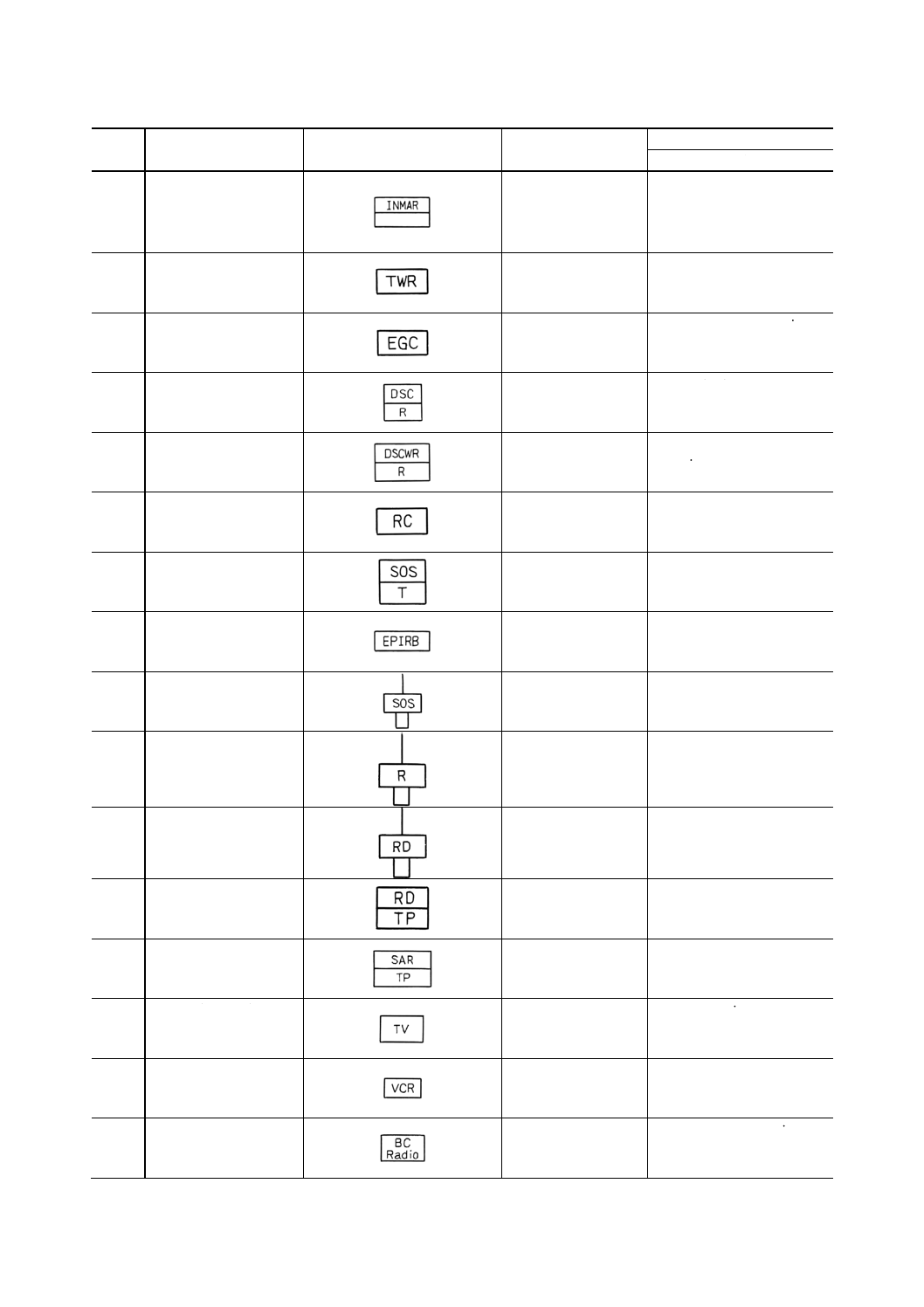
24.33 国際海事衛星通信装置
標準A形,C形の区別
が必要な場合は,
STD-A, STD-Cと記入
する。
international maritime
satellite communication
apparatus
24.34 双方向無線電話装置
two way radio telephone
apparatus
24.35 高機能グループコール
受信機
enhanced group call receiver
24.36 デジタル選択呼出装置
digital selective calling
system
24.37 DSC聴取受信機
digital selective calling watch
receiver
24.38 遠隔操作器
本体シンボルに追記
する。
remote controller
24.39 遭難自動通報設備
emergency position indicating
radio beacon
24.40 非常位置無線装置
emergency position indicating
radio beacon
24.41 遭難自動通報設備
(ブイ式)
emergency position indicating
radio beacons (buoy type)
24.42 ラジオ式ブイ
radio buoy
24.43 レーダ式ブイ
radar buoy
24.44 生存艇用レーダトラン
スポンダ
survival craft radar
transponder
24.45 捜索救助用レーダトラ
ンスポンダ
search and rescue transponder
24.51 テレビジョン受像器
television receiver
24.52 ビデオカセットレコー
ダ
video cassette recorder
24.53 ラジオ受信器
broadcasting radio receiver
22
F 8013-1991
2019年7月1日の法改正により名称が変わりました。まえがきを除き,本規格中の「日本工業規格」を「日本産業規格」に読み替えてください。
番号
名称
図記号
備考
参考
英文名称
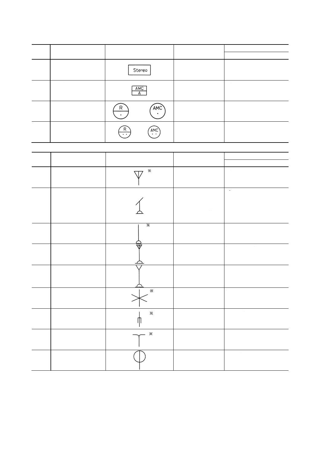
24.54 ステレオ
stereophonic gramophone
24.55 空中線共用装置増幅器
antenna multicoupler
amplifier
24.56 空中線共用装置接続箱
antenna multicoupler outlet
box
24.57 空中線共用装置接続箱
(電源付)
antenna multicoupler outlet
box (with source)
(25) アンテナ
番号
名称
図記号
備考
参考
英文名称
25.1
空中線
(一般)
antenna (general)
25.2
展張アンテナ
特に送信受信の区別
を必要とする場合は,
送信のときはT,受信
のときはRを傍記す
る。
wire antenna
25.3
ホイップアンテナ
whip antenna
25.4
トップローデングアン
テナ
top loading antenna
25.5
自立形アンテナ
self supporting antenna
25.6
ブラウンアンテナ
brown antenna
25.7
スリーブアンテナ
sleeve antenna
25.8
ダブレットアンテナ
doublet antenna
25.9
ループアンテナ
loop antenna
23
F 8013-1991
2019年7月1日の法改正により名称が変わりました。まえがきを除き,本規格中の「日本工業規格」を「日本産業規格」に読み替えてください。
番号
名称
図記号
備考
参考
英文名称
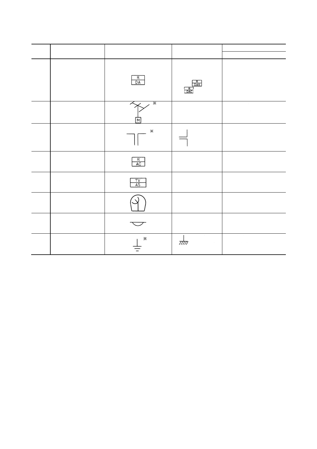
25.10 疑似空中線
特に抵抗又はコンデ
ンサの区別を表す必
要がある場合は
又は
のように表
す。
dummy antenna,
artifical antenna
25.11 テレビジョンアンテナ
(回転形)
television antenna with
driving motor
25.12 ダイポールアンテナ
垂直ダイポ
ールは,こ
のように表
す。
dipole antenna
25.13 アンテナ切替え器
antenna changer
25.14 テレビジョン空中線切
替え器
television antenna selector
25.16 ドームアンテナ
dome antenna
25.17 セーフティリンク
safety link
25.18 接地
外箱に接
する場合
earth(英)
ground(米)
24
F 8013-1991
2019年7月1日の法改正により名称が変わりました。まえがきを除き,本規格中の「日本工業規格」を「日本産業規格」に読み替えてください。
電気ぎ装委員会 構成表
氏名
所属
(委員長)
原 昌 三
三菱重工業株式会社船舶・海洋事業本部
勝 亦 二 郎
財団法人日本海事協会
藤 田 茂
昭和海運株式会社
村 上 嘉 昭
日本郵船株式会社
武 田 晴 雄
石川島播磨重工業株式会社船舶海洋事業本部
大須賀 実
川崎重工業株式会社船舶事業本部
志 村 博 行
住友重機械工業株式会社船舶海洋鉄構事業本部追浜造船所
鬼 頭 博 明
NKK総合エンジニアリング事業部鶴見製作所
竹 中 勇 六
日立造船株式会社船舶・防衛事業本部
福 井 泰 弘
三井造船株式会社船舶・海洋事業部
大 山 敏 夫
三菱重工業株式会社船舶・海洋事業本部
大 石 幸 明
大石電機工業株式会社
靏 谷 幸 雄
小糸工業株式会社
森 下 幸 作
株式会社高工社
神 谷 鍵 次
株式会社三英電機製作所
赤 嶺 淳 一
社団法人日本電機工業会
西 村 徹 哉
寺崎電気産業株式会社
佐 藤 康 宏
西芝電機株式会社
桂 木 義 夫
三菱電機株式会社長崎製作所
江 本 俊 夫
社団法人日本電線工業会
清 水 正 夫
藤倉電線株式会社
小 島 正 男
社団法人日本電子機械工業会
中 村 勝 英
アンリツ株式会社無線機事業部
宮 島 孫三郎
日本無線株式会社